DC etching tungsten tip preparation manual, version 1.0
Tomohide Takami, prepared on February 18, 2009
1) Anneal the tungsten wire (0.01 inch diameter, Alfa Aesar: Item #10408, 99.95% purity) in vacuum to eliminate the fiber structure in the wire. You do not have to anneal the wire, but you had better anneal it in order to avoid the etched tungsten tip from getting splashed or double like a tuning fork.
2) Cut the tungsten wire with a wire cutter. Check the sound when you cut the wire. Good cutting made higher cut sound, but bad one sounds like a smashed or lower cut sound. The cut end should be flat and clean in order to get a good shape tip.
3) Check the wire with an optical microscope. If the wire is contaminated with carbon due to the annealing process, wipe the wire surface using Kimwipes with acetone, or benzene and acetone if heavily contaminated.
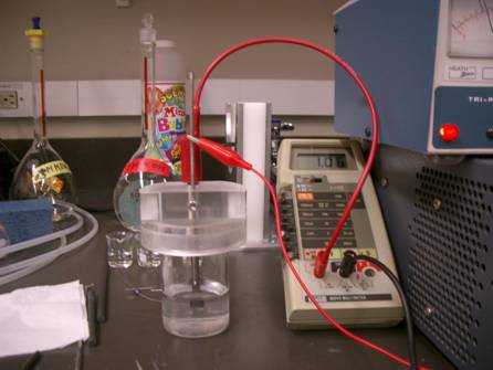
4) Set the tungsten wire to the stainless steel electrode. Do not screw the wire too much, or the wire is broken easily because the annealed wire is brittle. Note that the carbon rod next to the stainless steel electrode is the counterpart electrode.
5) Stir the flask of KOH solution upside down more than 3 times before use in order to keep a homogeneous concentration of the solution at any time. If the prepared solution was kept unmoved for more than a week, the concentration is low at upper solution and high at lower. Moreover, the quality of the solution changed due to the carbon dioxide dissolved from air. So do not shake the flask too much to avoid the carbon dioxide contamination. If the solution was prepared more than a month ago, you had better prepare a new solution because it contains carbonic acid so that the pH decreased and the conductance of the solution decreased, resulting in non-reproducible tip preparation.
6) Pour 0.88 mol/l KOH aqueous solution to the small beaker without spout (Kimble: 100 ml, Cat. No. 14020-100) at about 30 ml. Keep the volume of the solution the same as indicated the level on the beaker in order to have the same etching current. You can use lower concentration solution, e.g., 0.5 mol/l, but the concentration of the KOH solution influenced drastically the conductance during the etching process which determined the etched tip shape. When the concentration is lower than 0.4 mol/l, the initial conductance is lower than 2 mA, then the etching process is too slow and the etched tip shape sometimes gets strange. If the concentration is higher than 1 mol/l, the conductance of the solution is low and the initial etching current is more than 5 mA, resulting in instable etching.
7) Set the tungsten wire attached to the stainless steel rod above the solution and lift down the wire to approach the solution surface. When the wire edge touched the solution surface, dip in 1.5 mm to the solution. Do not rinse or flush the tungsten wire by applying higher voltage or negative bias voltage, or the etching condition changes and you cannot get stable etching. If the dipping is less than 1 mm, no reproducible tip shape is obtained; sometimes looks spiral like a soft ice-cream, or too long thin tip caused instable STM images. If the dipping is more than 3 mm, etching rate was slow and you cannot get an etched tip within an hour.
8) Make sure the level of counter carbon electrode (Graphite rods, diameter 1/4 inch, SPI Supplies, 01686-BA) dipped in the solution. The etching current may change if the level is changed.
9) Make sure that the DC power voltage is at 1.8 V, using a multimeter. Do not touch the voltage knob of the power supply (Heath Zemith, SP-2718) if you need not change the voltage. You should not start etching immediately if you turn the voltage knob. The supplying voltage is unstable just after the change of the voltage set. You had better wait at least a minute to let the voltage supply stable if you touched the voltage knob. Then switch on DC power supply to start etching. No bubbles at the tip side and subtle ones are at the carbon counter electrode. If you set the voltage lower than 1.5 V, the etched tip surface is rough caused unstable STS. If you set the voltage higher than 3 V, the etching rate increased but unstable etching so that the shape of the etched tip is not smooth.
10) Watch the etching current with the set multimeter. If the initial current, 30 s after switch on, is more tha 5 mA, the etching rate is too fast and not stable caused strange shape of the etched tip. The change of the initial current is usually due to the change of the concentration of the solution. You had better change the solution with the suitable concentration for etching, 0.88 mol/l. If the current was unstable, contamination is on the tungsten wire; you had better change the wire. If the decrease of the current is more than 0.02 mA/s, the etching process is too fast. If you cannot obtain a stable current decrease, stop the etching and make sure the setting; stable wire connection, solution, electrode, and wire. Automatic current shutdown circuit helps you not to miss to switch off the etching. The shut off current is set at 0.5 mA. If the shut off current is more than 1 mA, tiny wire remains on the tip and the obtained tip is too long and unstable for use. If the shut off current is less than 0.2 mA, the etched top is round and not sharp enough to use for STM.
11) Rinse the wire with Millipore water immediately after etching because the wire just after etched is covered with etched contaminants. You should prepare 3 beakers and rinse it three times. The made tip might get ruined if you did not rinse well.
12) Keep the made tip in your tip container.
Tips for tips
Here shows the photos of etched tips with various conditions. If you obtained
a bad tip, refer to the photos bellow and check the cause of the bad tip.
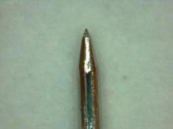
This is an AC etched tip. It worked very well for imaging, but tunneling spectra showed unstable at higher voltages more than 1V. Sputtering made the tip worse for imaging but tunneling spectra was slightly better than before sputtering. I am not good at AC etching; some can make good and reproducible but I could not control the hydrogen gas bubbles appeared around the etching wire.
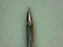
This is an AC etched tip with a bad etching condition due to the high concentration of the solution. Instable etching is usually due to the over-power supply. Better to monitor the etching current to avoid the bad etching. If you had such a bad tip, check the concentration of the solution and the voltage.
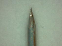
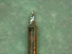
This is a DC etched tip by changing the voltage during the etching; 1.5 V initially and changed to 3.5 V. The surface of the shank part etched at 1.5 V is rough whereas that etched at 3.5 V is metallic but the etching was instable resulting in the discrete shape.

This is a DC etched tip at 3 V. The shape is the mix of those at 1.5 V and 3.5 V. The threshold of the change of etching process is around 3 V, but the reason of the bad tip was a high current during the etching; 10 mA at the initial current. The high current is due to the high concentration of the solution; more than 1 M.

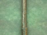
This is a DC etched tip a 1.5 V. It looks fairly good but the surface of the shank is rough, resulting in the tunneling spectra from this tip instable at higher voltages more than 1 V.
This is a DC etched tip at 1 V. The etching rate is lower than that at higher voltages, resulting in longer shank. Both the image and tunneling spectrum were instable.
This is a DC etched initially at 1 V and changed to 10 V. The low voltage etching results in rough shank surface, and high voltage etching results in short tip.
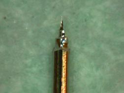
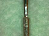
This is a DC etched tip at the same condition as that we got a good tip. There is a carbon flake stuck on the tip shank, which caused the high current (5 mA) and instable etching. So the check of the initial current is important to avoid making a bad tip.
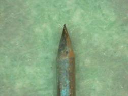
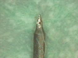
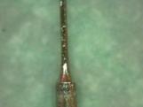
This is a DC etched tip at 1 V. The color of the top end is black, which indicates carbon contamination was on the tip during the etching. Moreover, rough 111 facets appears on the shank.
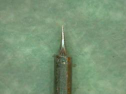
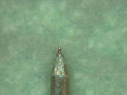
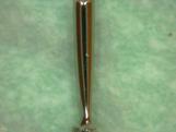
This is a DC etched tip at 1.8 V. Typical good tip but only the inferior point is that the tip shank was too long that cause instable. We can control the shank length by changing the dipping length into the solution and the voltage.
Typical DC-etched tip at high initial current (10 mA) and high voltage (5 V). The etching rate depends on the surface index in this condition; higher at larger surface index and minimum at 111. Therefore some 111 facets appear on the shank. This condition may help to find out how to make a clean and flat tungsten (111) surface with electrochemical etching.
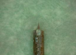
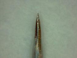
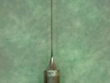
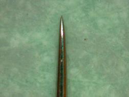
This is an ideal DC etched tip. Shank is short but the top is sharp. The condition was 3.5 V and 0.75 M KOH solution and 2 mm dip into the solution.

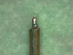
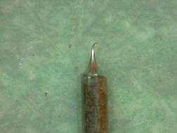
This is a DC etched tip. The bad shape was due to the carbon contamination stuck on the tip.
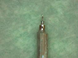
This is also a DC etched tip with a carbon contamination stuck on the tip end during the etching. When you have an instable current during the etching you had better stop etching and check the wire surface first because the high current is usually due to the carbon contamination on the tip. If it is not the problem, check the concentration of the KOH solution.
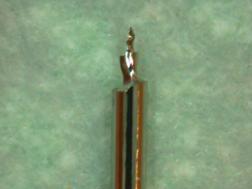
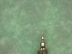
This is a DC etched tip at 3.5 V and low KOH concentration (0.5 M) after flushing the wire with hydrogen bubbles by applying a negative voltage for 10 s. Current was not fluctuated during the etching but the obtained shape was strange, like a soft ice-cream. Low concentration sometimes caused a bad tip shape; it should be more than 0.5 M.
This is a DC etched tip at 3.5 V and low KOH concentration (0.5 M) after flushing the wire with hydrogen bubbles by applying a negative voltage for 10 s. Current was not fluctuated during the etching but the obtained shape was strange, like a soft ice-cream. Low concentration sometimes caused a bad tip shape; it should be more than 0.5 M.
A series of DC etching process.
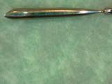
The drooped DC etched wire end in the solution when the dipping was 10 mm. We can use the dropped wire in the solution if the dropped tip top did not touch anything.
This is a typical DC etching at 3.5 V and high initial current (10 mA). The current jumped up and down several times and the history of the current changes is recorded on the tip shank like an annual ring.
This used to be a good tip. Do not ask what I did.
A typical DC etched tip at 5 V and large initial current (15 mA). High initial current caused discrete etching. The concentration of the solution was 0.5 M but the carbon contamination floating on the solution surface caused the high current.
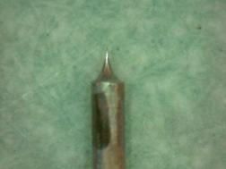
At last, I will show a typical good tip. The initial etching current was 3.6 mA and drop off current was 0.6 mA. The dipping length into the solution was 1.2 mm, applied 1.8 V to the wire. 0.88 M KOH aqueous solution.
Summary of the tips:
Take care etching current during the etching. When you have a large initial
current more than 5 mA, stop the etching and fix the cause of the large current.
The cause of the leak current may be
1) contamination on the wire surface
2) contamination floating on the solution surface, or
3) concentration change of the solution.